

|
A Programmable Prototype to Build Turing Machines | |
| Home | Alan TURING | History | Turing machine | The actual experimental prototype | Some diagrams of Turing machines for this prototype | Presentations | Presse | Simulator | A new machine |
|||||||||
| Machines | Ideas | Description | How the machine operates | Technologies | First Turing machine | Easy | Calculations | Sequences | Interesting | Colleges | University | Talks | Videos | Contact | ||||
|
In Turing's paper, we find the sentence : |
|
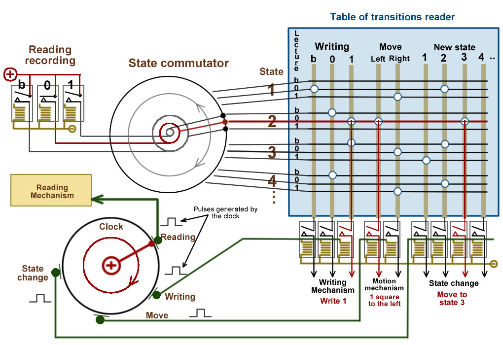 |
The scanned symbol T(r) is recorded into one of the three b, 0 and 1 relays. The m-configuration qn is a state of the machine. Each line in the table of transitions reader is powered by an electrical wire. The state commutator connects the 3 wires from the reading recording relays to the 3 wires of the table of transitions reader. In the example of the diagram on the left, the reading is 0, only the wire from relay 0 is supplied with electric current. The state commutator is in position 2. Only the horizontal line in red in the diagram is supplied with electric current. This line is determined by the current state and the reading recording. The behaviour of the machine consists of 3 possible operations:
The rotation of the clock contactor triggers the necessary operations by successively sending a pulse to:
Conclusion : The whole wiring diagram is simply a logical transposition of the concept described by Alan Turing. |
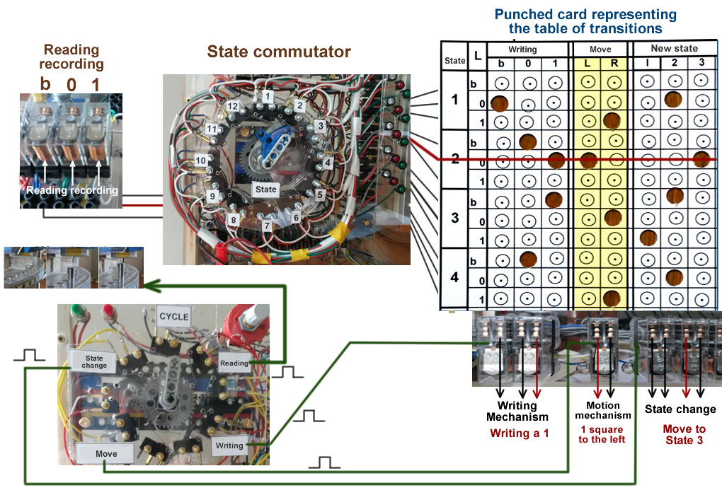 |
Please note :
The punched card reader representing the table of transitions could have been made with a set of electrical wires and plugs, like with the first telephone exchanges. The relays used to transmit the operations to be performed to the various mechanisms are dual relays. For example, one relay is enough to transmit the move selections (Left or Right). 6 relays are enough to transmit the selection of a new state among 12. The red potentiometer to the right of the clock is used to adjust the rotation speed and the pulse frequency. The microprocessor's internal clock regulates the rate at which instructions are executed. If in today's PCs, the frequency is several Gigahertz, for this prototype, it is about 0.5 Hz. But all the components have to operate faster, or at least as fast as the clock frequency. This has not always been for the case for computers and it is not the case for this prototype. The writing/reading heads, the mechanism of the disk move and that of the state change can be slower. "Return" circuits temporarily stop the clock until the selected component has performed its task. |
|
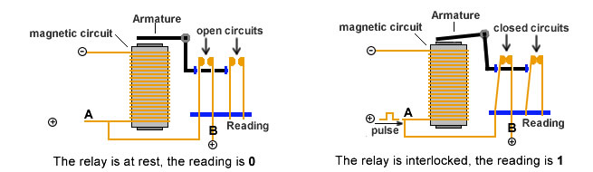
Using a relay as elementary memory (1 bit):: A relay with at least 2 contacts is used. When an electric pulse is sent to point A in the relay's coil, the armature is lowered so that the various contacts communicate with each other. In the diagram below, the first contact provides electric current from point B to the coil entry. Thus, the relay remains self-supplied. Break the circuit at point B to put the relay at rest. To read this "memory relay", send out a pulse to the second contact. If the relay is at rest, the current does not flow and the reading is 0. If the relay is interlocked, the current flows and the reading is 1. If the power supply is switched off, the relay is put at rest and the memory is lost. In a computer, the relays are replaced with transmitters, but the operating principle is the same. |
 |