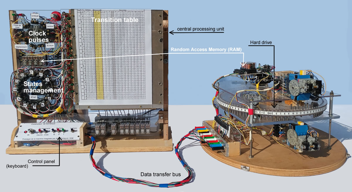
A programmable prototype to achieve Turing machines

Home Alan TURING History Turing machine The actual experimental prototype Some diagrams of Turing machines for this prototype Presentations Presse Contact A new machine
Machines Ideas Description How the machine operates Technologies First Turing machine Strings Calculations Sequences Interesting Colleges University Talks Videos

The Tape

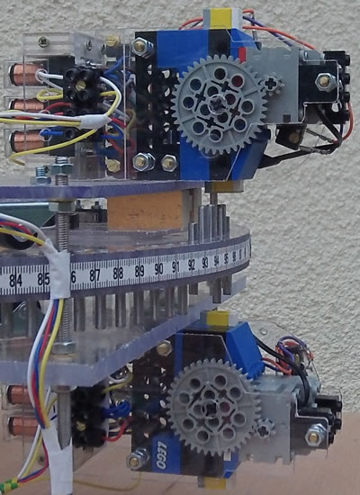
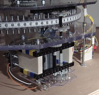
The tape is divided into one hundred small cylinders which can assume the three following positions, alphabet: {b,0,1} ::

  • b : The cylinder is completely down.
  • 0 : The cylinder is halfway down (7mm).
  • 1 : The cylinder is fully up (14mm).
Please note: The tape is "folded onto itself" in a circle. If the number of cylinders is finite (100 units), the tape itself is limitless!
 
Also note that in order to get 100 equidistant graduations on the circumference of a 100cm circumference disk, I used a tape measure which is slightly extensible.
This extensibility proved helpful because it allowed me to make a 1 meter + epsilon circumference disk.
With the measure tape, I could match 0 with the 100 graduation.

Writing Mechanism

Two mechanisms are placed respectively above and below the tape fitted with the cylinders.

  • Writing a b : The head above pushes the cylinder completely down.
  • Writing a 0 : Both heads are operating, each pushing the cylinder halfway.
  • Writing a 1 : The head below pushes the cylinder fully up.
Given the choice that was made, writing a 0 does not require a preliminary reading.

Reading Mechanism

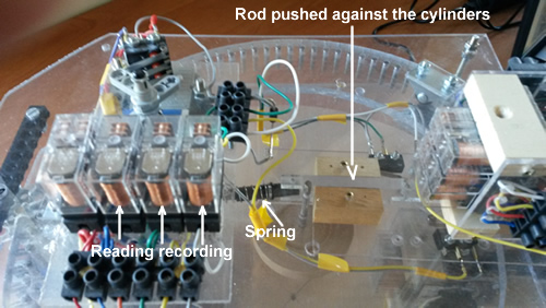
A rod is thrust against the cylinders and depending on its position at the end of the thrust, the system will indicate whether the cylinder stands for a b, 0 or 1.
The result from the reading is temporarily "stored" in 3 of the 4 relays that can be seen on the picture.


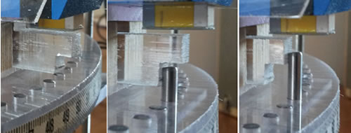
The various thrusting positions against a cylinder:

  • Blank : The cylinder is completely down, the rod is fully up.
  • Zero : The cylinder is halfway up. The rod is thrusting with its first notch.
  • One : The cylinder is in upward position. The rod is pressing with its second notch.


Tape Movements

An electric engine drives a small cog-wheel whose cogs are inserted between the cylinders to rotate the disk (Turing tape).

  • Moving to the left : The tape shifts one cylinder to the left.
  • Moving to the right : The tape shifts one cylinder to the right.
Just like in the reading phase, it is the result of one line in the table of transitions that indicates what movement to make next.

Please note : It was easier to rotate the disk than to move the reading head !

The programmes : The Table of transitions
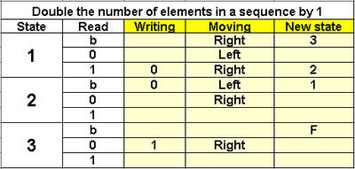
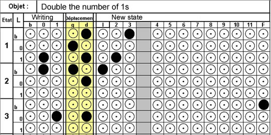
This table tells the machine what to do, depending on the state it is in and the result from the reading.

  • State: Column 1 it is the state number
  • L (for �Lecture� � reading in French): Column 2 it is the result of the {b,0,1} reading.
  • Writing: Column 3: it is subdivided into 3 columns b, 0 and 1 (writing b, 0 and 1).
  • Movements: Colum 4: it is subdivided into 2 L and R columns (for Left and Right).
  • New State: Next columns: 12 columns for eventually selecting a new state.
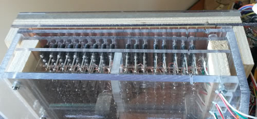
To transmit to the machine, holes are punched into selected squares. The punched card is simply inserted into the reading system comprising of 612 pins which are pressed against this card. Electrical contacts are established where the holes are, and the current is transmitted to the writing, moving and state selection systems.


Sizing:
  • Number of lines : 3 lines for each state; here 12 states and 36 lines
  • Number of columns : Writing: 3       Movements: 2       New state: 12, for a total of 17 lines
  • Total number of punches : 36 x 17 = 612


The operation clock cycle

he rotary system performs a series of operations listed chronologically below until it is halted by the final state.

  • Reading : It is carried out automatically at each round.
  • Writing : The machine writes an element of the {b,0,1} set.
  • Movements : It moves one square to the left or one square to the right.
  • State selection : The selection is determined by the table of transitions. If no new state is selected, the machine does not change state.

State commutator

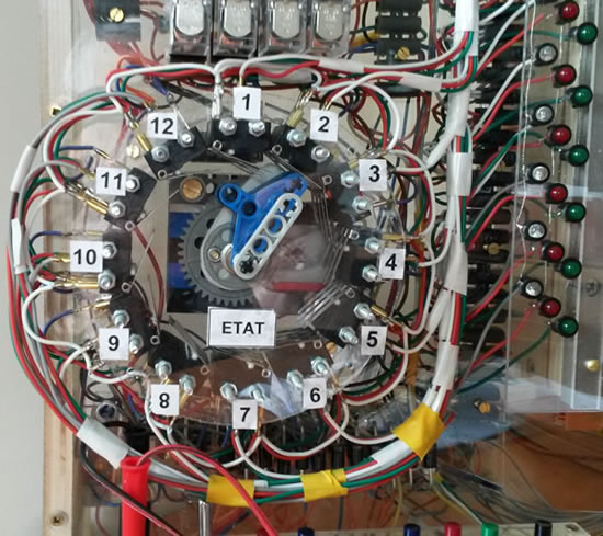
The machine comprises 12 states

  • State 1 : It is the initial state (selected by pressing the red button above the operation cycle).

  • State 12 : It is the final state which halts the machine.
For each state, the mechanism provides the result of the {b,0,1} reading to the table of transitions.

Control Panel

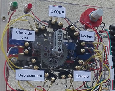
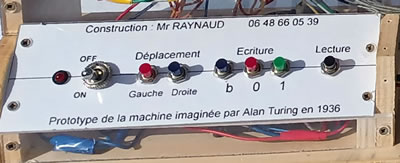
To run tests, the various functions can be activated from this control panel.

To enter the data that will be processed by the machine, there are two possibilities:

  • You can use the control panel: Movements and writing.
  • You can position the cylinders manually.

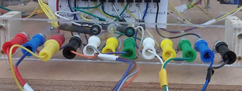
Data Transfer BUS Wire harness with electrical connectors

  • Power supply Two 6-volt wires (+/-)
  • Writing process 3 wires standing for b,0,1
  • Reading process 1 wire to launch the reading phase and 3 wires to return the value of the reading stage to the central processing unit.
  • Moving tape 2 wires to differentiate the left from the right shift.

Random Access Memory It is totally erased when the power supply is off

  • Reading relays : They temporarily store the results from the reading.
  • Writing down relays : To limit the movements to 7mm or 14 mm.
  • State relays : They temporarily store the new state to be selected.
  • RAM capacity : 16 bits (i.e., 2 octets)

Power Supply:

  • 6 volts off 220v mains supply
  • It could be replaced by batteries.